

Category: Stepper Motor
Real Mounted Short Metal Shaft Stepper Motor ◆Special anti-vibration design. ◆Compact design: Ф30mm x 7.6mm. ◆High precision: 1/12° step angle.
+86-755-23067791
1. Overview
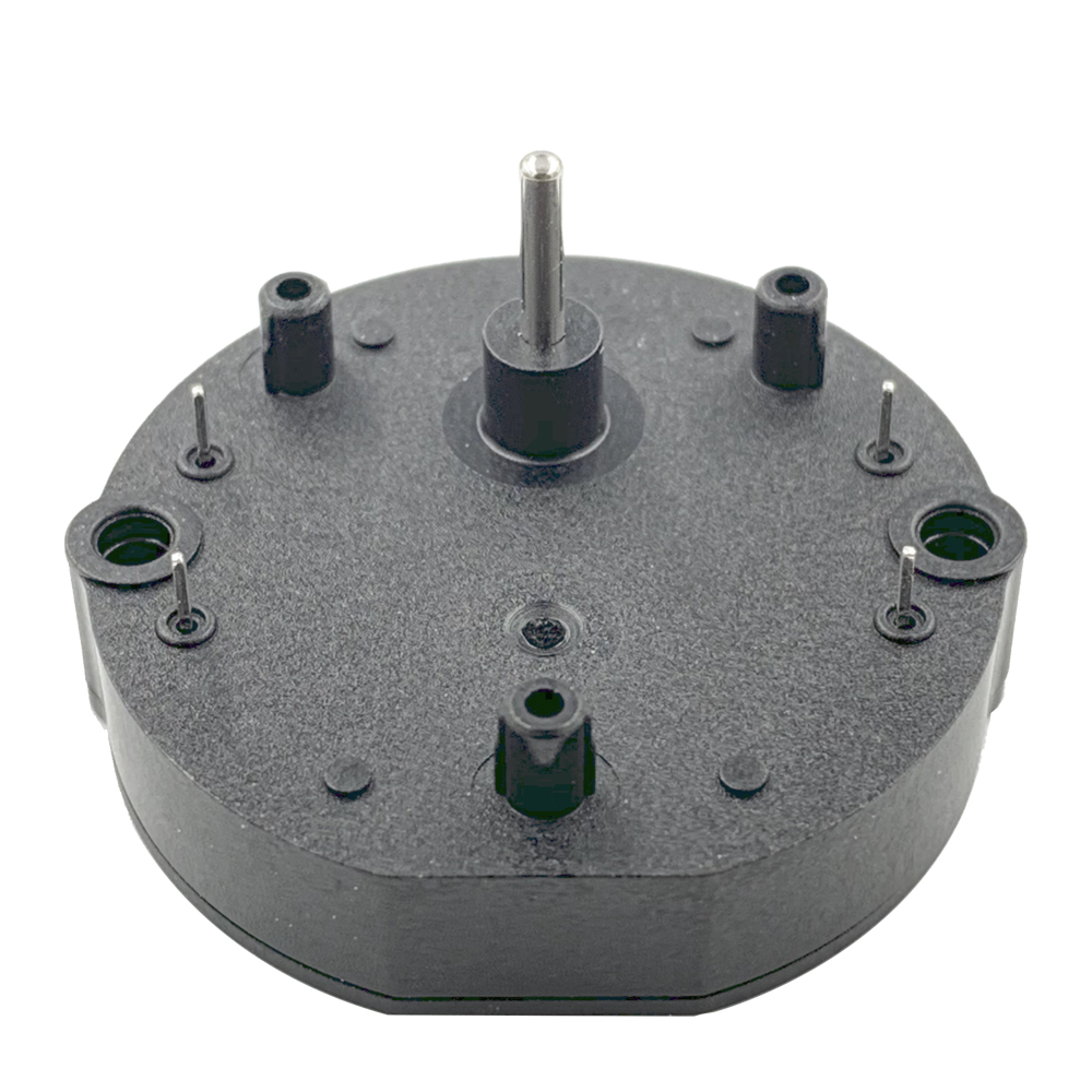
MDR29 series stepper motor is specially designed for indicator components (such as pointer) used to drive vehicle instrumentation and other precision indicator devices that directly accept the digital signal of the system, drive the pointer to a location to indicate the required parameters, without Digital-to-Analog Converter.
There is a built-in 4-gear transmission system with 1/180 deceleration ratio to achieve the precision as high as 1/12° in micro-step mode.
Patented design and high precision components enable the MDR29 series stepper motor to have strong dynamic torque, extremely low operating noise and power consumption, as well as sturdy structure and long service life.
2. Main Feature
3. Typical Application
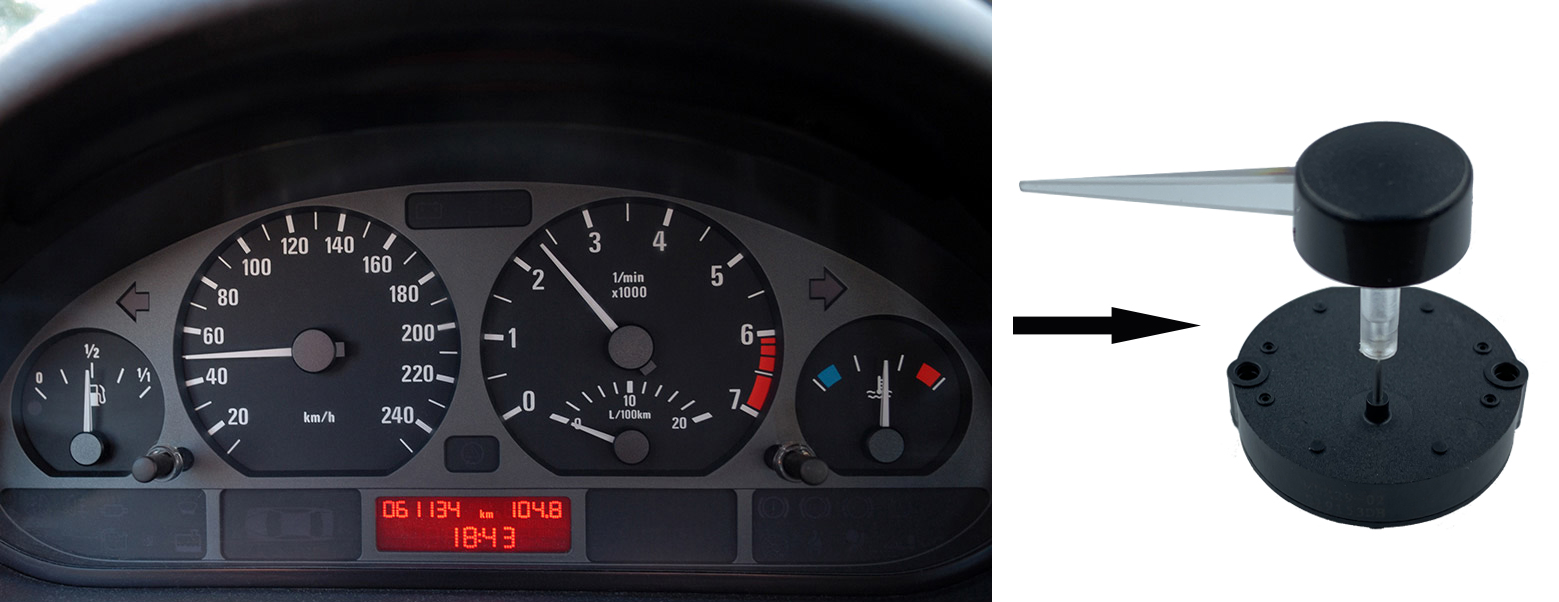
The typical application of MDR29 series stepper motor is used for automobile instrument cluster, motorcycle dashboard.
4. Operating Principle
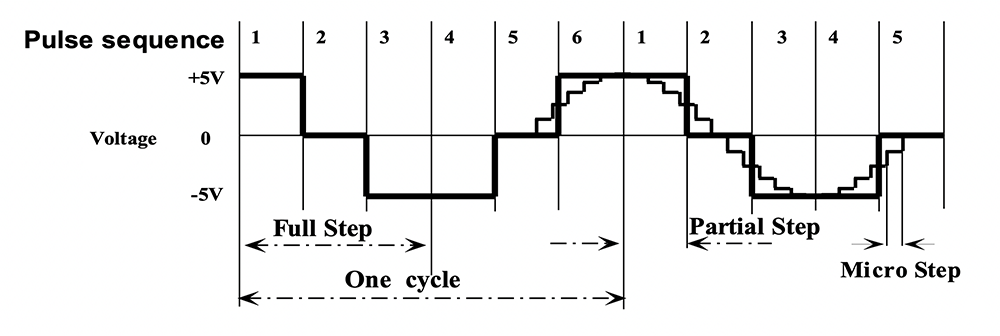
Through the built-in 4-gear transmission system with 1/180 deceleration ratio, the pointer shaft will rotate 1° while the rotor rotates 180° driven by a full-step driving signal. And in partial-step mode, the pointer shaft will rotate 1/3° while the rotor rotates 60°.
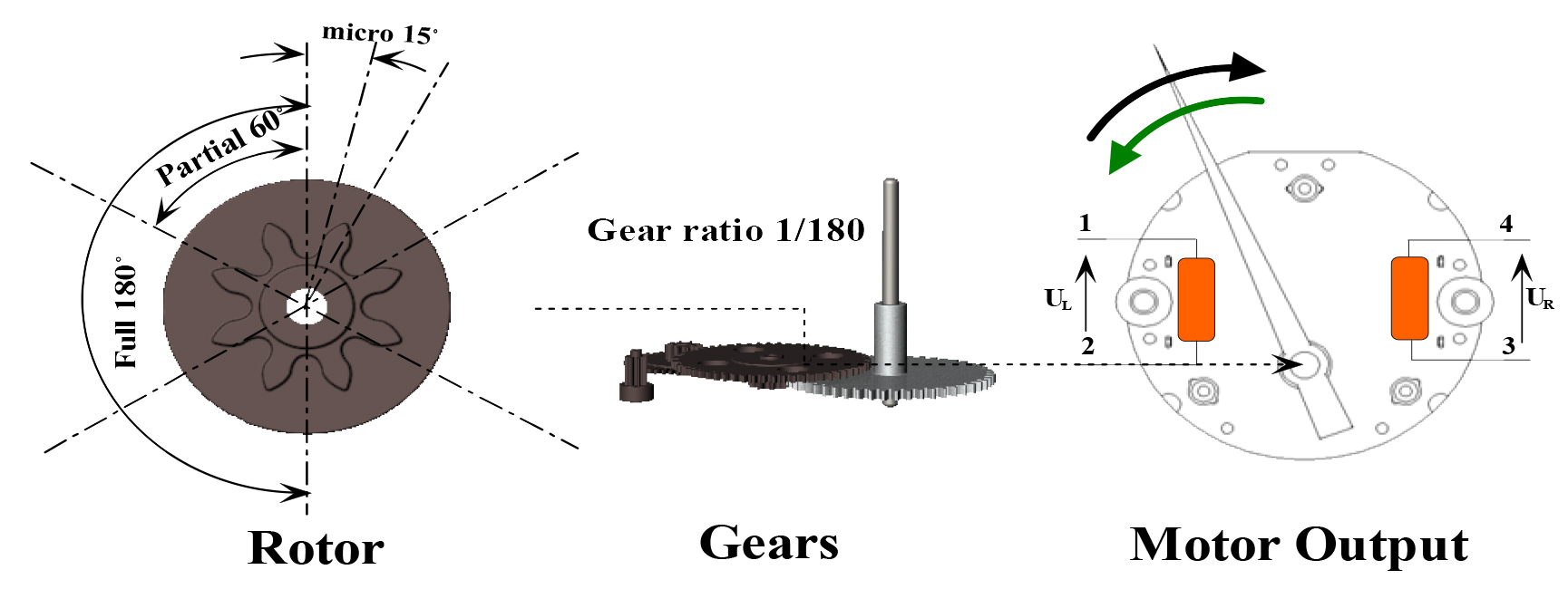
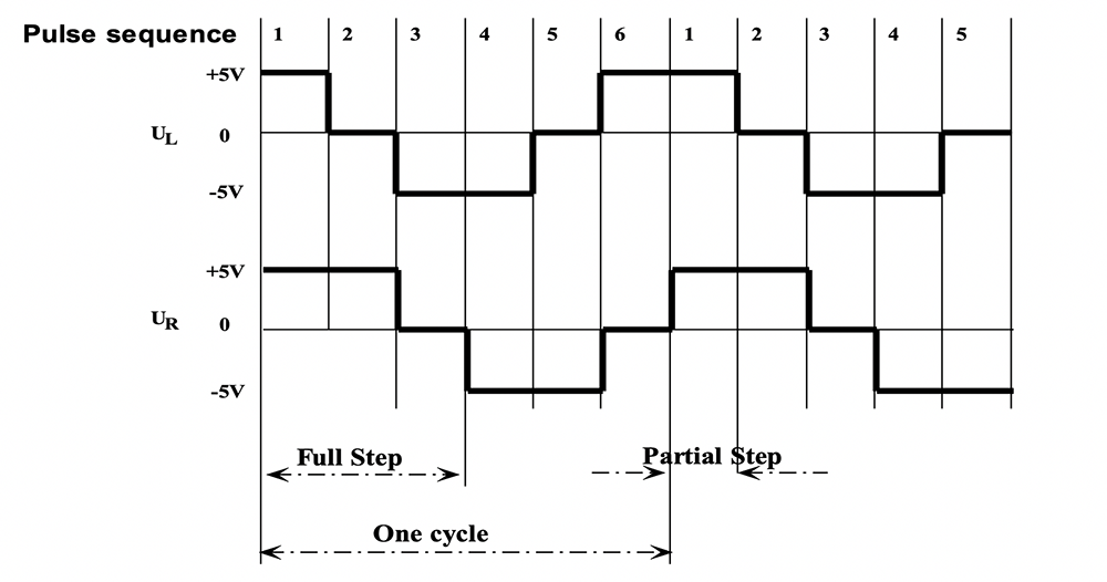
In order to make motor run more stably and decrease the noise especially when pointer loaded on pointer shaft, micro-step mode is recommended. The micro pulse sequence, which is more precise and near to sine wave, could drive pointer shaft to rotate 1/12º at each micro step.
|
Parameter |
Symbol |
Test Conditions |
Min. |
Typ. |
Max |
Unit |
|
Operating Temperature |
Ta |
|
-40 |
|
105 |
ºC |
|
Coil Resistance |
Rb |
|
260 |
280 |
300 |
Ω |
|
Operating Current |
Im |
fz=200Hz |
|
15 |
20 |
mA |
|
Magnetic Saturation Voltage |
Ubs |
|
|
|
9 |
V |
|
Start-Stop Frequency |
fss |
JL=2x10⁻⁷kgm2 |
|
|
200 |
Hz |
|
Maximum Driving Frequency |
fmm |
JL=2x10⁻⁷kgm2 |
|
|
600 |
Hz |
|
Dynamic Torque |
M200 |
fz=200Hz |
0.9 |
1.1 |
|
mNm |
|
M400 |
fz=400Hz |
0.75 |
0.9 |
|
mNm |
|
|
Static Torque |
Ms |
Ub=5V |
3.5 |
4.0 |
|
mNm |
|
Noise Level |
SPL |
|
|
39 |
42 |
dB(A) |
|
Angle of Rotation |
β |
with internal stop |
|
|
320 |
Degree |
|
without internal stop |
|
|
360 |
Degree |
||
|
Gear Play |
σ |
|
|
0.7 |
1.0 |
Degree |
|
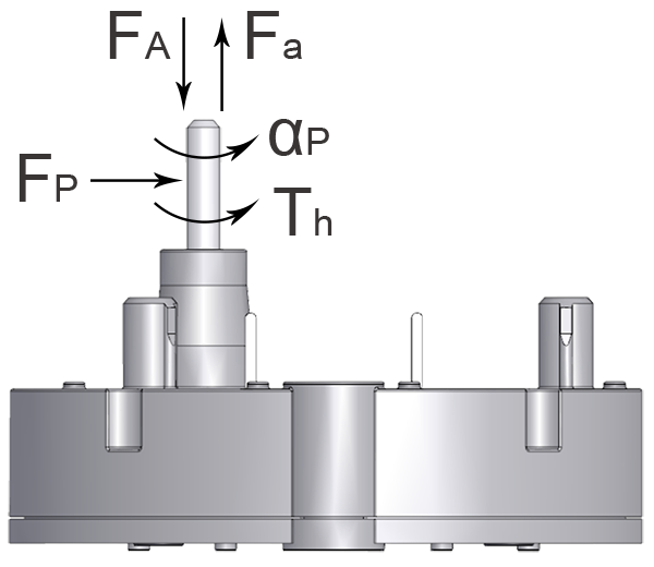
Force Allowed on the Pointer Shaft |
||||||
|
Axial Force (push) |
FA |
|
100 |
120 |
|
N |
|
Axial Force (pull) |
Fa |
80 |
100 |
|
N |
|
|
Perpendicular Force |
FP |
12 |
15 |
|
N |
|
|
Imposed Acceleration |
αP |
|
1000 |
|
Rad/s2 |
|
|
Holding Torque |
Th |
90 |
120 |
|
mNm |
|
Note: fz = testing frequency, JL = testing pointer inertia, Ub = operating voltage

Copyright © 2020 MDR International Limited. All Rights Reserved. Designed by BATEN